Phase Detection in Digital Signals
Phase Detection is an important concept in radar signals. It could be used to determine the time delay between radar signals and this time delay could be used to infer the distance of the object from the radar, which is the main aim of the radar. Even if it is assumed that transmitted signal and received signal should be same, there occurs to be noise. I was assigned to implement phase detection for FPGA’s for my internship in Summer 2010 as they are used for radar signal processing. They can do complex and real-time processing, are cheaper than computers, portable, low power consumers. However, I did not go into implementation directly. I need a simulation which would yield promising results. Then, I could implement in VHDL. I chose Matlab and implemented three different methods. (This would decrease to two in VHDL). I will compare these methods as well, but it cannot be deduced that some method always or even usually perform better than some other method based on the results provided. There are a numerous reasons, but I will just mention few of them. Firstly, this is just a simulation after all. Secondly, the simulation takes into consideration only one of the signal is noisy(received), which may not hold true in general. Moreover, there are constant parameters which may favor some method over other ones. Before giving details of the methods, I am urged to mention an important concept that two methods use, Schmitt Trigger.
Schmitt Trigger
Schmitt Trigger is a comparator with two different threshold values. When the signal goes over High Threshold, it yields 1(HIGH). It remains 1 until signal goes below Low Threshold, it yields 0. It remains 0, until signal goes over … as it could be seen the figure below.
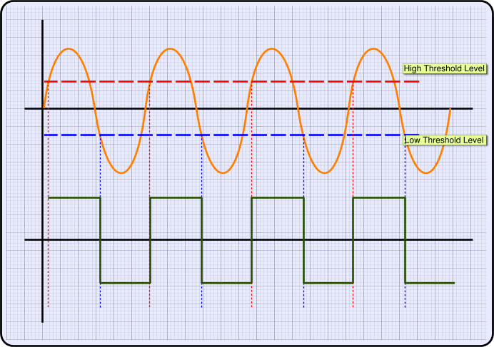
In analog implementation of Schmitt Trigger, there is a feedback mechanism which uses hysteresis to adjust its threshold values. In this implementation, they are constant. Schmitt Trigger is used to prevent noise when analogous signal is transformed into a digital(binary) one. It prevents oscillation in the binary signal which is convenient and makes the binary signal robust to noise. Consider the figure below, A is a basic comparator. B is a Schmitt Trigger. Any fluctuation in the border of A resultss in oscillation in the digital signal. This is the general case for noisy signals. However, fluctuations in border B does not change digital signal since digital signal needs to wait for high threshold value or low threshold value to change.
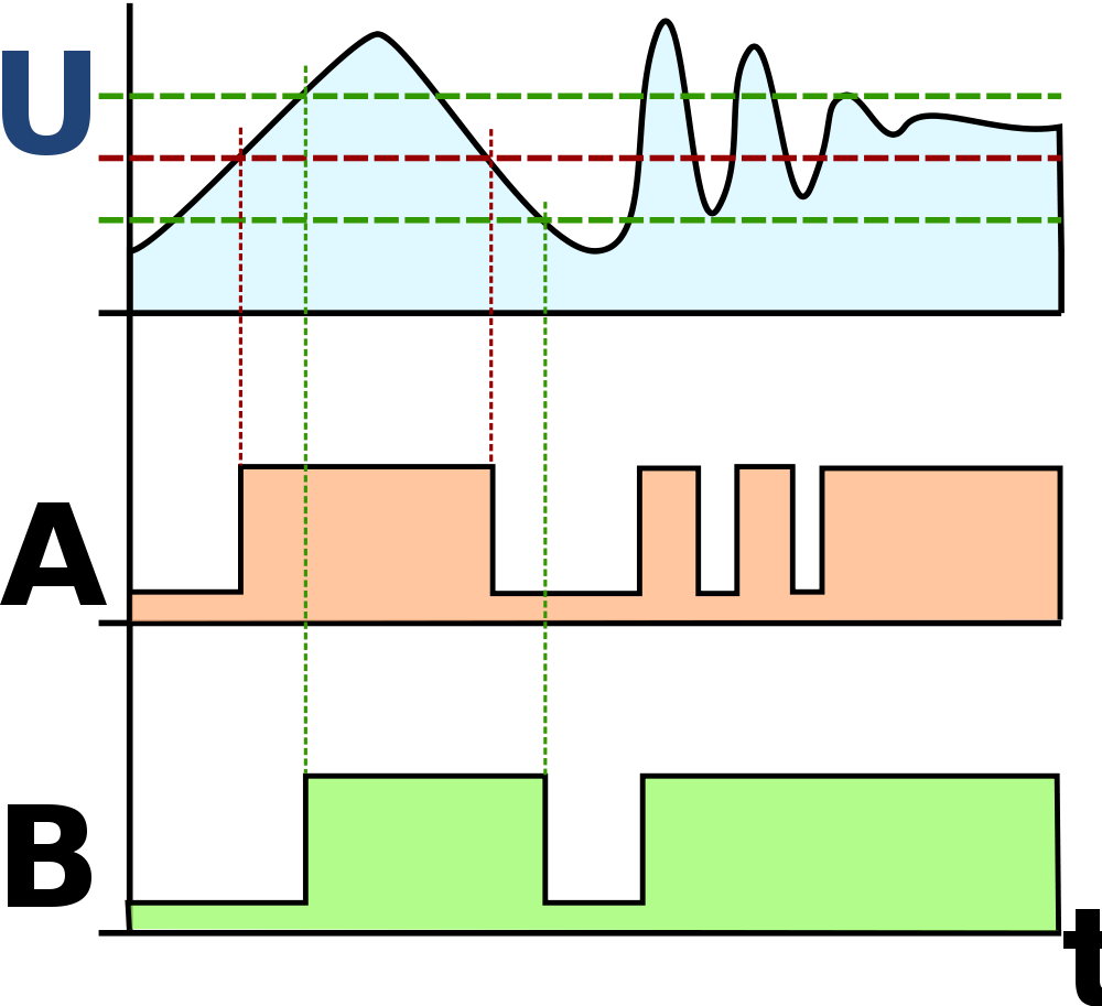
It is important to note that if noise level is higher than the difference of two thresholds, schmitt trigger does not provide robustness to noise. It is still better than a basic comparator, though. Therefore, noise level should be taken into consideration when setting up the threshold values.
PulseLag Method
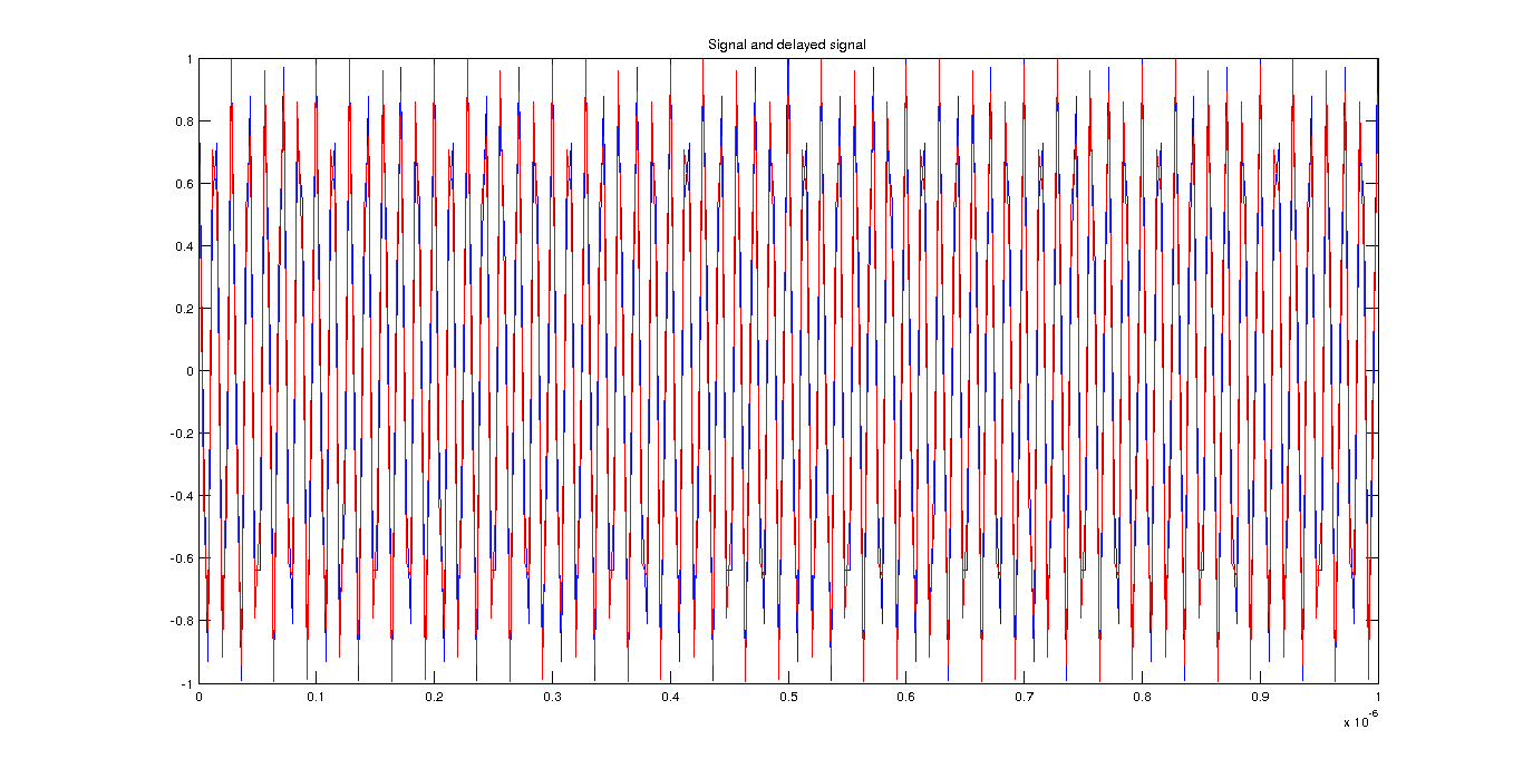
In this method, we multiply both signals $ f_c $ with another sinusoid, but a lower frequency $ f_{down} $ Then, low-pass filter this signal in order to get low frequency part.
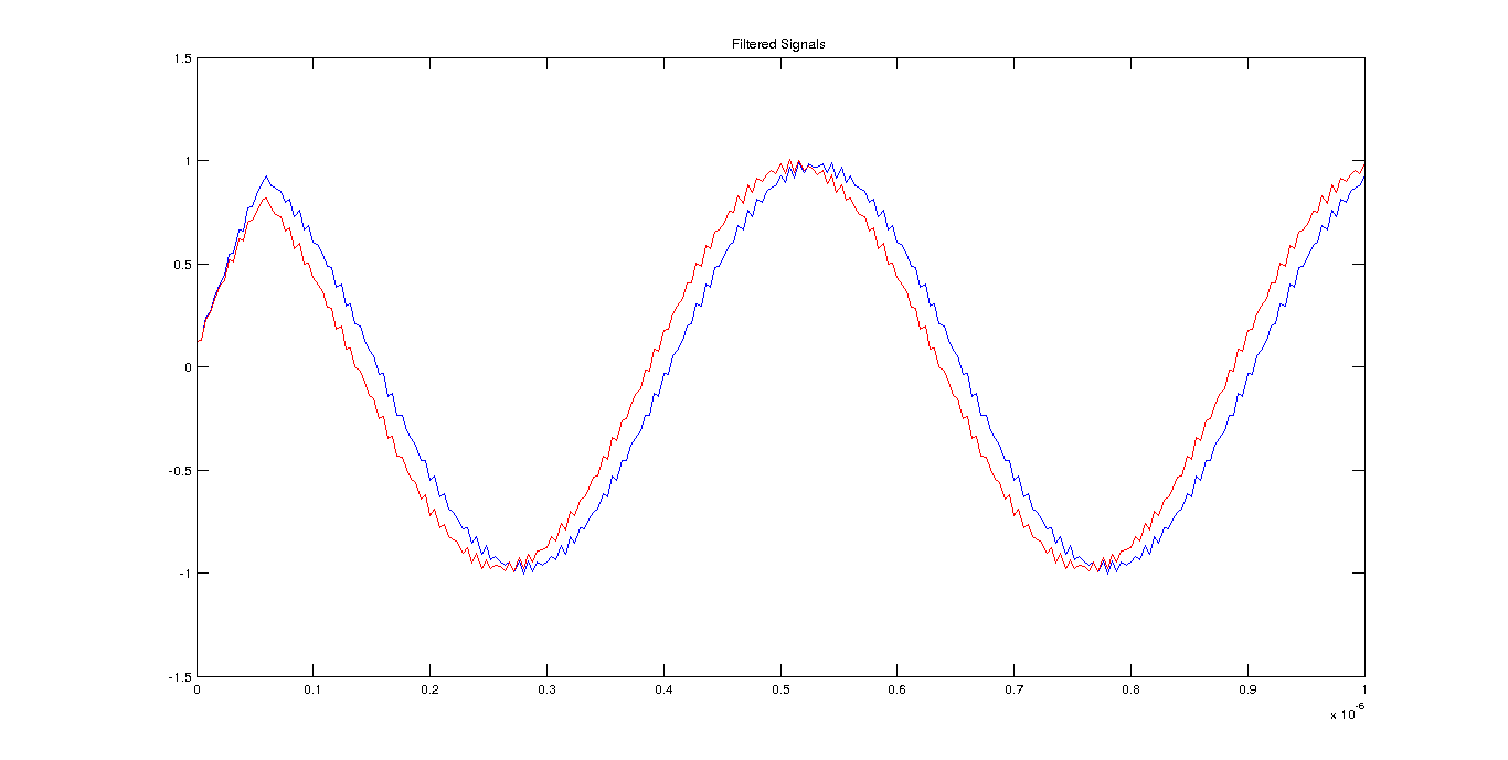
After filtering the signal, we put it into Schmitt Trigger. Then, we get their difference which also gives time delay.
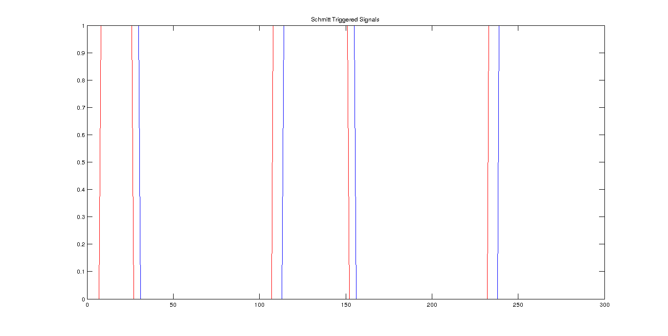
We need the ratio of the (number of times first signal is 1 and second signal is 0) over the total time. Then, we need to divide this ratio to $ f_c $ to find time delay. I apply 0.5 nanosecond delay in the signal and it will be constant for the other methods as well, for noiseless case method measures 4.5714e-10. For noise coefficient = 0.1, method measures 5.1429e-10. For noise coefficient = 0.2, method measures 8.0000e-10, which is not even close. Even if noiseless and when noise is small, this method performs well, for noisy cases, it is not robust to noise.
Multiplication Method
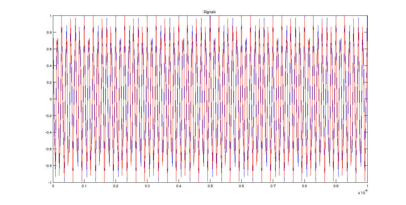 If we multiply two signals with each other, we have a high pass term and a phase term if they have both the same frequency.(noiseless case)
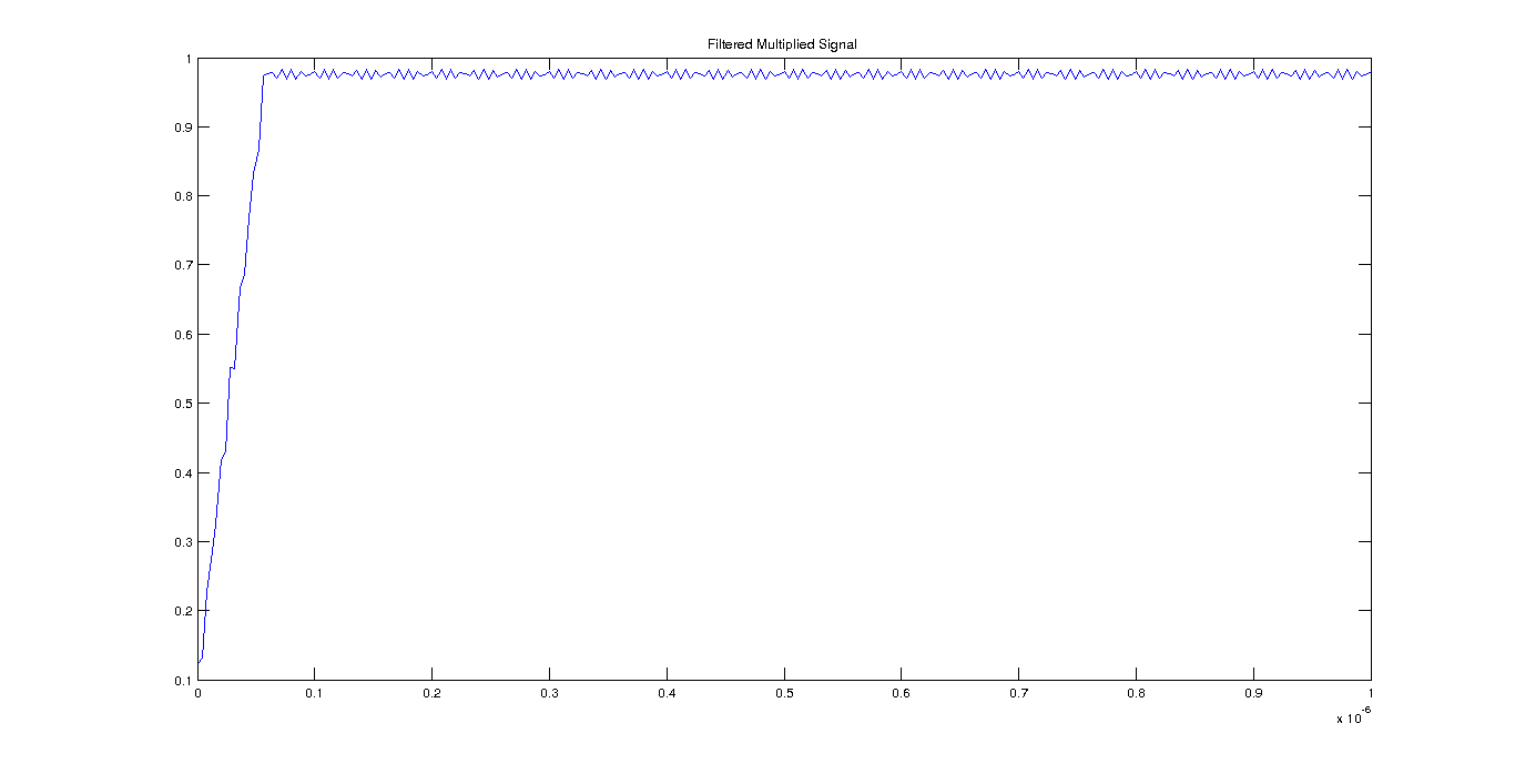 If we get inverse sin or cosine of the multiplied signal
[Alt text](https://raw.github.com/bugra/Phase-Detection/master/img/multiplication_method3.png " Inverse of Filtered Multiplied Signal") and take mean of the signal(after some heuristics), divide by , then we get a time delay.
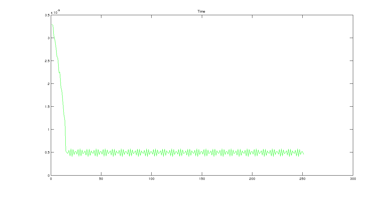
For noiseless case method measures 4.9639e-10 which is quite close. For noise coefficient = 0.1, method measures 4.6909e-10. For noise coefficient = 0.2, method measures 5.8330e-10, which is quite close for such a high noise.
FFT-Based Method
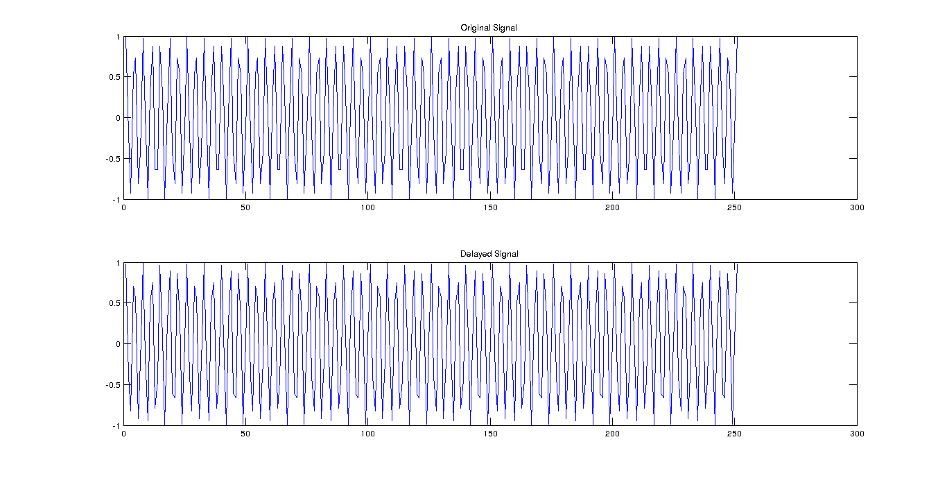
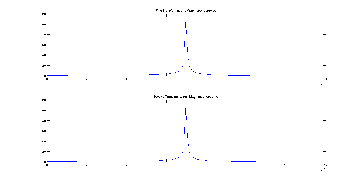
FFT can be written in a Discrete Fourier Transform: and It is important to note, in the magnitude response, the phase will be one. Therefore, it will not affect the magnitude response. Since we send periodic signals, the maximum of frequency response will occur at the dominant frequency which is the period of the signal. As the magnitude response will be same, we could just take the phase response of the same index in FFT to find the phase information between the signals. Original and delayed signal(0.5e-9) signals are given below.
Magnitude response of the signals are given below.
Phase response of the signals:
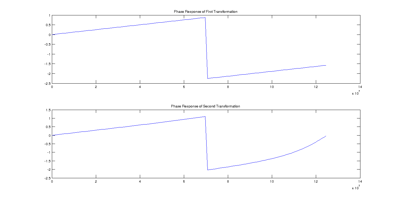
When we take the phases of the both signals and subtract, we get the phase difference. Time delay is only the ratio of phase difference over $ 2 * pi * fc $. For noiseless case method measures 4.9656e-10 which is quite close. For noise coefficient = 0.1, method measures 5.1161e-10. For noise coefficient = 0.2, method measures 3.9221e-10, which is not very close.
Result
For noiseless case, all of the methods perform quite well. For medium noise(n = 0.1), FFT-Based and PulseLag method; for high noise, Multiplication method performs better.
Code
All of the code and images used in this note is available in the here. Moreover, implementation of Multiplication and FFT-Based method in VHDL is also available in here.